Waterproofing Procedure for Penetrator Devices
On the end cap of a watertight enclosure for underwater equipment, there are often bulkhead penetrator devices such as underwater switches, depth sensors, indicator lights, temperature sensors, etc. These components can either be mounted directly on the end caps or routed externally through cables.
There are two main waterproofing methods for external devices:
- Axial Seal
- External Subsea Coupling Tube
1. Axial Seal
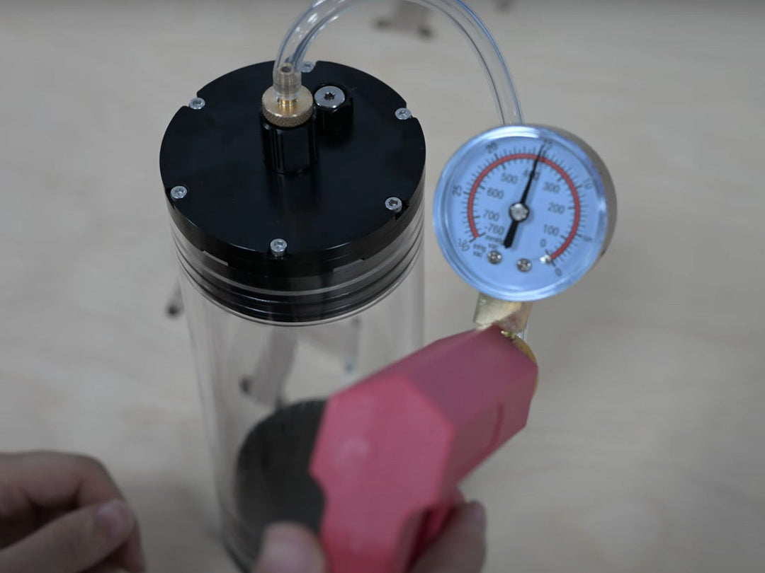
If the bulkhead penetrator device does not have specific placement requirements, it is typically installed directly onto the bulkhead without external cables. In this case, the device must be sealed axially to ensure waterproofing. It should not be fully submerged in water without proper sealing. The internal cables connect to the internal space of the watertight enclosure.
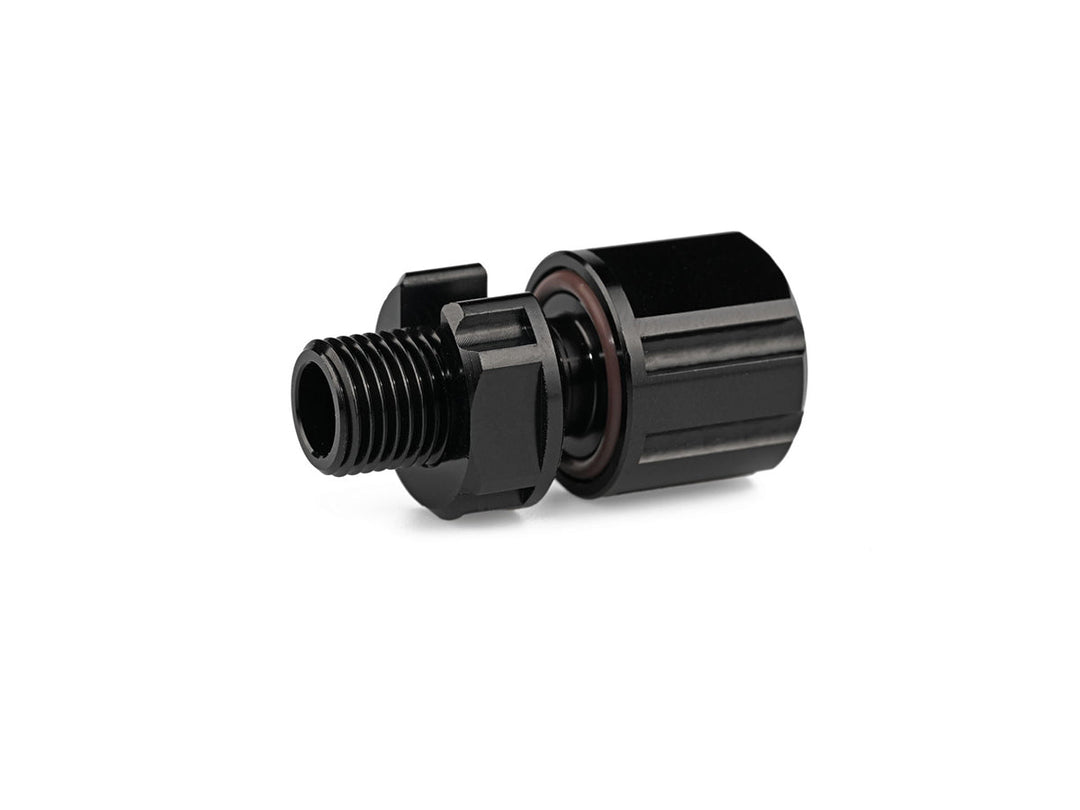
These bulkhead penetrator devices are usually shaped like threaded bolts. They feature an end-face sealing groove at the base, which creates a waterproof seal when the nut is tightened through the end cap and the o-ring is compressed. This method supports waterproofing up to 1,000 meters in depth.

Image: Penetrator Sealing Diagram
The red frame in the above profile image shows the location of the end-face seal for an underwater penetrator. Waterproofing is achieved by tightening the device onto the end cap with nuts, which compresses the o-rings.
Points to Note:- Ensure the surface of the end cap that contacts the O-ring is clean, scratch-free, and free of debris.
- Place the O-ring within the sealing groove. You can apply watertight grease, such as O-Ring Lubricant – MOLYKOTE® 111 Compound , to help the O-ring adhere and remain in place. The grease must be waterproof and insoluble in water.
- Properly tighten the nut. Do not insert extra O-rings or parts that reduce friction. However, anti-slip washers can be used to enhance grip.
- The mounting hole must not be oversized. It should only allow the bolt to pass through without creating excess clearance that causes wobbling or displacement.
| Recommended Size | M6×1 Penetrator | M8×1 Penetrator | M10×1 Penetrator | M14×1.5 Penetrator | M16×1.5 Penetrator |
|---|---|---|---|---|---|
| Bulkhead Through Hole Size (A) | Ø6.1 ± 0.1 | Ø8.1 ± 0.1 | Ø10.1 ± 0.1 | Ø14.1 ± 0.1 | Ø16.1 ± 0.1 |
| Hatch Cover Thickness (B) | 6 | 14 | 13 | 18 | 17 |
| Surface Range (C) | 15 | 17 | 20 | 26 | 32 |

Image: Mounting Hole Dimension Drawing
2. Subsea Coupling Tube

Image: Subsea Coupling Tube Diagram
When one end of the watertight enclosure is not accessible by hand, the cable for, for example, a Subsea M10 Rotary On/Off Switch must be extended to another position. In such cases, an external Subsea M10 Coupling Tube and an underwater cable are used to extend and waterproof the connection.
A Subsea Coupling Tube consists of a main tube and a gland head locking nut. The underwater cable enters through the locking nut and is filled with glue inside the tube. The tube provides both structural support and adhesive containment. The locking nut secures the cable and prevents excessive bending or displacement of the adhesive.
Example Method – Subsea M10 Rotary On/Off Switch:
- Select an underwater cable with an outer diameter of 7–8 mm for an M10×1 coupling tube. Cut the cable to a suitable length and strip the outer insulation.
- If the cable's outer diameter is less than 7 mm, wrap the locking nut section with tape or heat-shrink tubing to ensure centering and contact.
- Trim the switch cable and solder it to the extended cable. Cover the solder joint with heat-shrink tubing.
- Clean all bonding surfaces (inside the tube and the cable surface) with alcohol.
- Route the underwater cable through the coupling tube and secure the switch to the tube.
- Insert the cable fully into the tube and pour in adhesive. For optimal results, a marine-grade epoxy such as Loctite Epoxy Marine is recommended. For non-load-bearing applications, sulfur-based sealants like 3M2131 may also be used. Screw on the locking nut.
- Let the adhesive fully cure before moving or handling the assembly.
Refer to the assembly diagram. Cables must be fully surrounded by adhesive and centered to ensure proper sealing. Once completed, the penetrator device can be safely submerged and routed to external positions.
Product reference: Subsea M10 Coupling Tube


Leave a comment