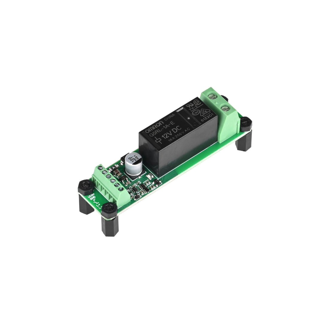


The Toggle Relay Control Module converts a momentary signal—such as from a tap switch—into a latched output, enabling the control of powered devices using a single press-to-toggle interaction. Tap once to turn the device on, and tap again to turn it off. This relay-based module is ideal for applications where traditional latching switches are impractical, particularly in underwater or sealed environments.
It is specifically recommended for use with the Subsea M10 Tap Switch (Non-Latching) and the Subsea Embedded Push Button Switch (Non-Magnetic), allowing these low-power inputs to toggle high-current devices like lights, solenoids, and pumps. The onboard circuit includes a 30 ms debounce delay to reduce false triggers, along with a long-press (1 second) shutoff function for added control in turbulent or impact-prone environments.
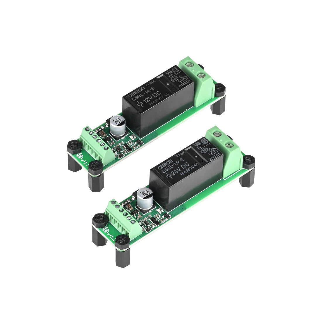
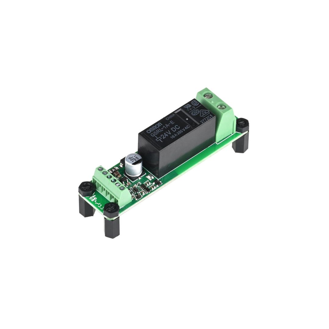
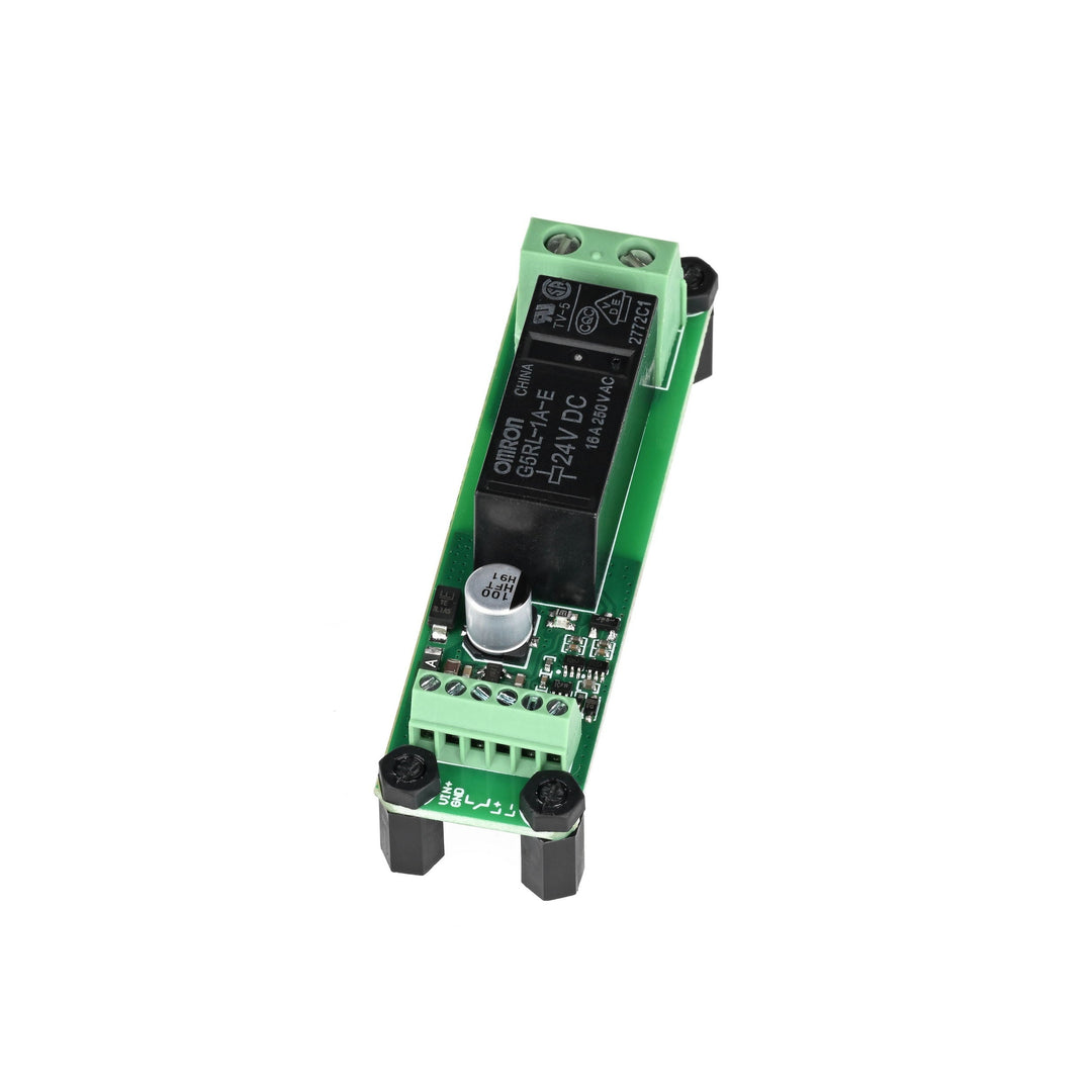
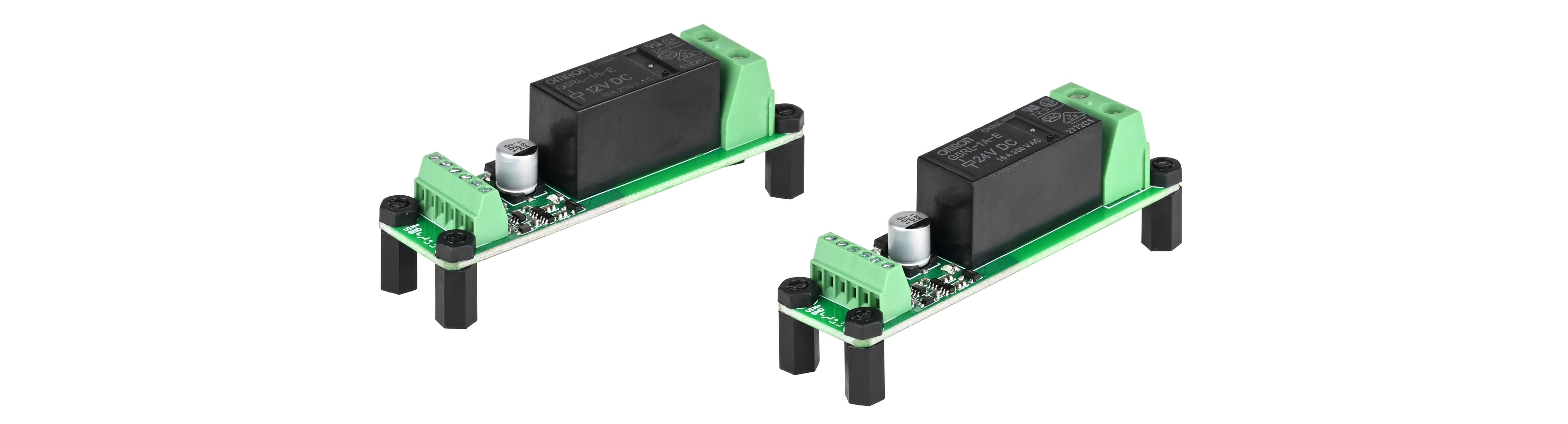
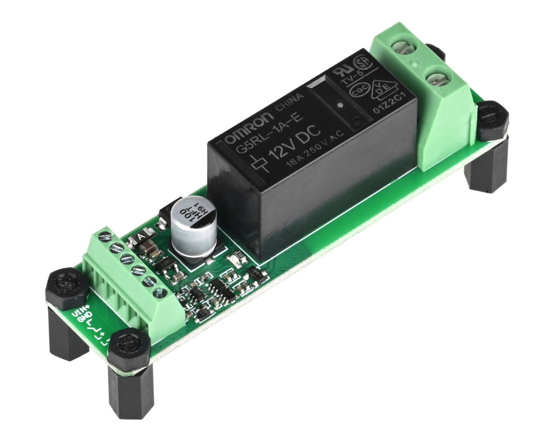
Two versions of the module are available: a 12V model compatible with 3S battery systems (9.6–12.6V), and a 24V model for 6S systems (19.2–25.2V). Both versions feature reverse-polarity protection, a high-current relay (up to 16A), and a status indicator LED that reflects the current output state. The relay uses an SPST-NO contact configuration and is fully isolated from the coil circuit for safe switching.
While optimized for underwater systems, the module is also suitable for surface use in any setup requiring simple latching control from a momentary input. For best results, ensure proper power supply stability and consider using surge suppression when switching inductive loads like motors or relays.

This relay module is designed to work with low-power momentary inputs. For underwater use, pair it with the M10 Tap Switch below.
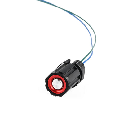
Subsea M10 Tap Switch (Non-Latching)
A depth-rated, momentary mechanical switch that activates when tapped and resets when released. Fully compatible with this relay module for toggled control of underwater lights, pumps, solenoids, and other devices.

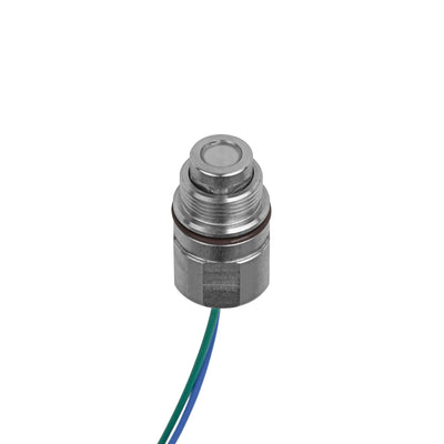
This relay module is fully compatible with the Subsea Embedded Push Button Switch (Non-Magnetic), a momentary, self-resetting control input built from non-magnetic 316 stainless steel for interference-free operation near sonar and navigation systems.
Common use cases include diver-held sonar triggers and underwater remote controllers, where magnetic interference must be avoided. When paired with this module, the switch gains latched on/off functionality, long-press shutoff, and debounce protection—making it ideal for controlling subsea lights, pumps, and mission-critical systems.
| Specification | 12V Push Button Relay | 24V Push Button Relay |
|---|---|---|
| Relay Model | G5RL-1A-E DC12V | G5RL-1A-E DC24V |
| Weight | Approx. 22 g | Approx. 22 g |
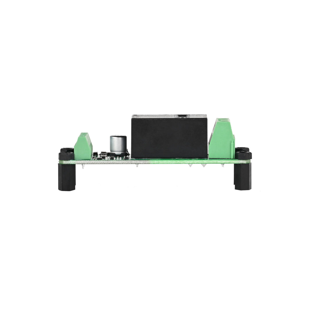
| Dimension | 72 × 20 mm | 72 × 20 mm |
| Height | 20 mm | 20 mm |
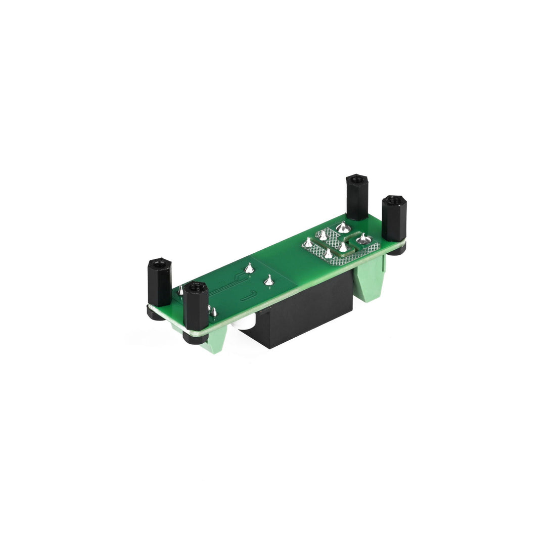
| Mounting Hole Distance | 14 × 66 mm | 14 × 66 mm |
| Mounting Hole Size | Ø3 mm | Ø3 mm |
| Supply Voltage | 3S Battery (9.6–12.6 V) | 6S Battery (19.2–25.2 V) |
| Rated Current | 50 mA | 30 mA |
| Quiescent Current | 12 µA | 14 µA |
| Button Debounce Time | 30 ms | 30 ms |
| Turn-off with Long Press | 1 s | 1 s |
| Rated Load | AC 250 V 16 A / DC 24 V 16 A | AC 250 V 16 A / DC 24 V 16 A |
| Maximum Switching Current | 16 A | 16 A |
| Contact Type | SPST-NO (1a) | SPST-NO (1a) |
| Contact Resistance | Below 100 mΩ | Below 100 mΩ |
| Action / Reset Time | Below 15 ms | Below 15 ms |


Precautions for Use
● When a DC power supply with fluctuations is included, please use a power supply with fluctuations below ±5%. If the fluctuation of the coil current becomes larger, the operating voltage will change greatly, and a buzzer will also be emitted.
● If the voltage applied to the coil is insufficient, the relay does not operate or the operation is unstable, resulting in reduced contact life, welding, and other contact failures.
● Drop or impact may result in false triggering and damage to the relay.
● When the relay is powered on, there is a risk of electric shock by touching the charging part.
● Maximum current on contact switch: Due to the influence of electromagnetic energy stored in inductive loads, the switching capacity of inductive loads is usually lower than that of resistive loads. When the load is inductive, use appropriate surge suppression according to the actual circuit and actual load under the actual conditions of use.
Load Type and Inrush Current
Differences in the type of load will result in different inrush currents when the relay is engaged.
| Load Type | Inrush Current |
|---|---|
| Resistive Load | 1 time of steady-state current |
| Motor Load | 5~10 times of steady-state current |
| Capacitor Load | 20~40 times of steady-state current |
Wire Diameter
The diameter of the conductor should be determined by the load current. If the wire is thin, it will burn out due to abnormal heating of the wire.
| Permissible Current (A) | Cross-sectional Area (mm²) |
|---|---|
| 6 | 0.75 |
| 10 | 1.25 |
| 15 | 2 |
| 20 | 3.5 |
Is it necessary to supply a separate operating power supply to the circuit board when converting the tap switch to self-locking use?
Yes, a separate power supply is required to operate the relay control board. This can be directly supplied from a battery or other regulated power source.
What types of switches can be connected?
This module is designed to work with self-resetting (momentary) tap switches.
What is the difference between the MOS electronic switch board and the relay?
A relay has no leakage current when open and offers full electrical isolation between the control side (coil) and the switched circuit. This makes it more suitable for applications requiring electrical separation or low leakage.