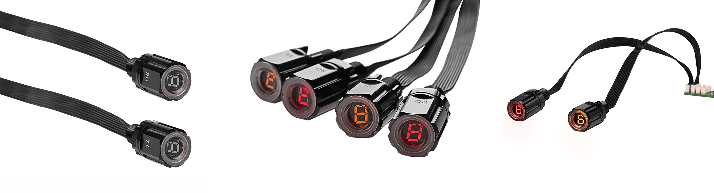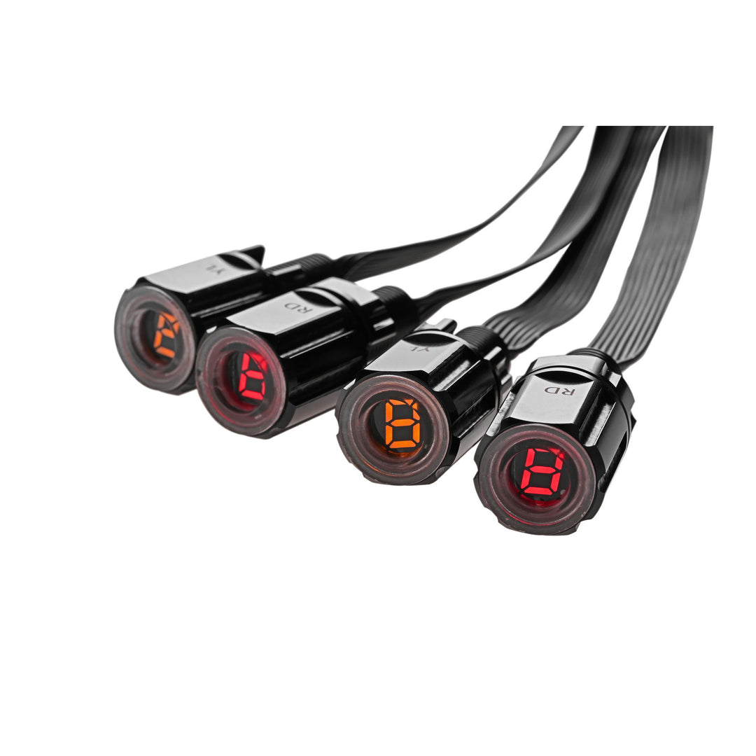


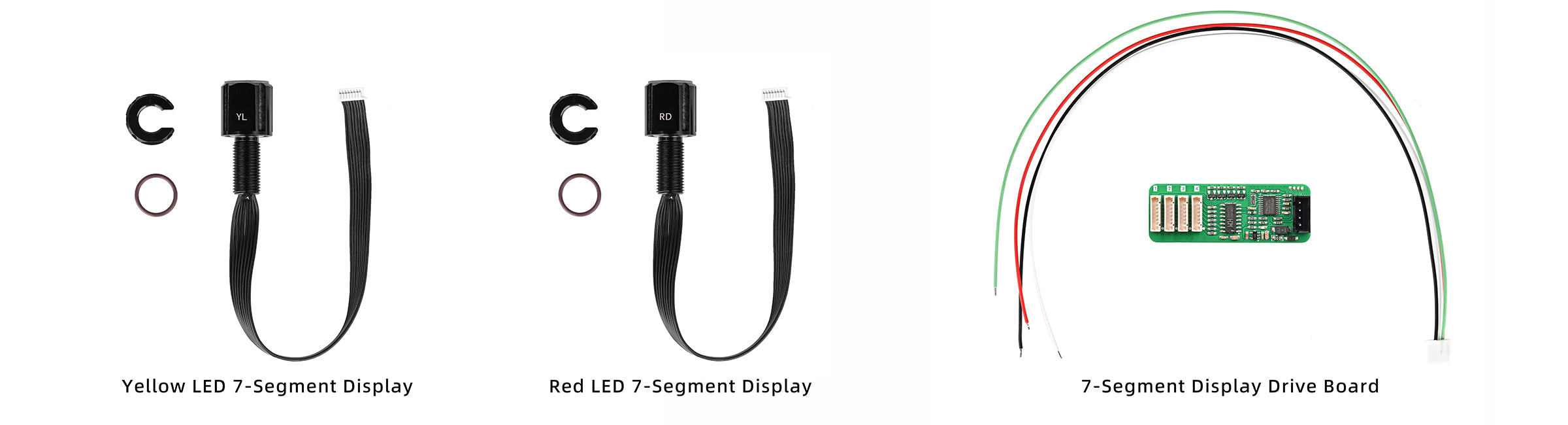
Engineered for use in subsea environments, the LED Display Module provides immediate visibility of system electrical parameters. It connects to the appropriate Blu-Sub Driver Board to receive live signal input, enabling real-time monitoring of power performance in ROVs, enclosures, or tethered setups.
The module’s form factor and encapsulation make it ideal for embedded applications where sealed visibility is critical. It is designed to be mounted within enclosures or exposed panels and supports integration into broader monitoring systems through its signal-driven input interface.

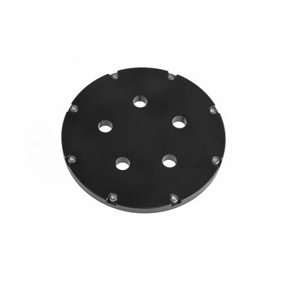
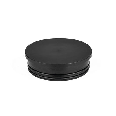
Subsea Aluminum End-Cap
Select models include unthreaded M10 holes or blank positions that can be drilled to mount the Subsea 7-Segment Display. Secured with a rear locking nut for a watertight seal.
Subsea Acrylic End-Cap
Cost-effective, transparent end-cap option offered in blank or CNC-drilled thru-hole configurations for mounting the Subsea 7-Segment Display. Used with the Subsea Aluminum Flange and secured with a rear locking nut for panel sealing.
Subsea Polymer Flange & End-Cap
Easily user-drilled to accept the M10-threaded 7-Segment Display. Suitable for shallow-water or surface-rated enclosures where modularity is preferred.
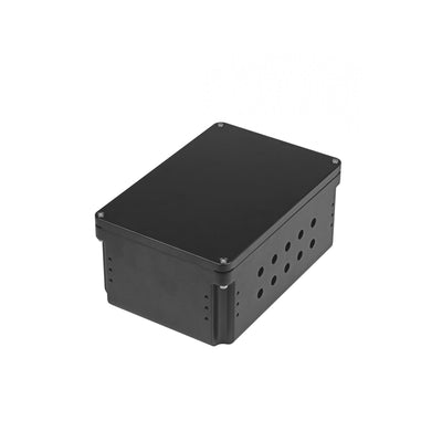
Subsea Watertight Enclosure Box
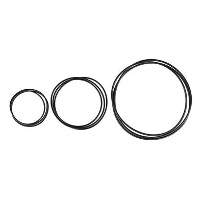
Pre-drilled with 20 unthreaded M10 ports, enabling direct installation of the 7-Segment Display using the included nut and O-ring for panel sealing.
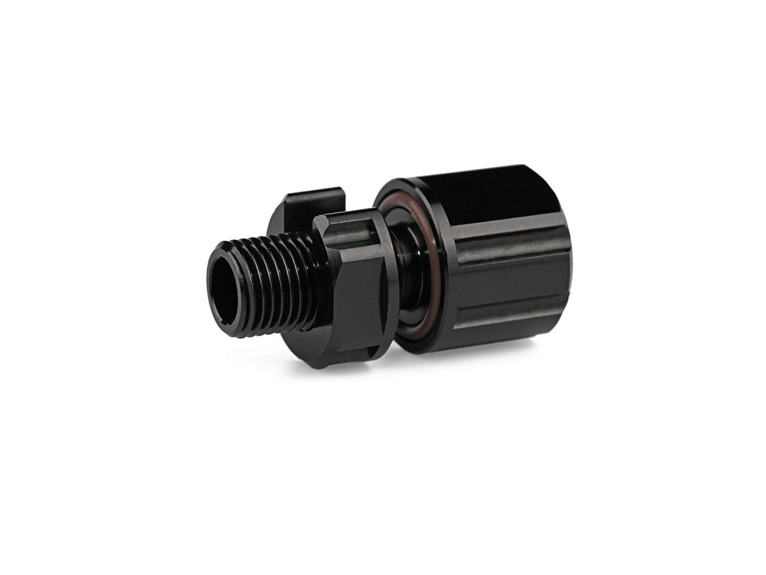
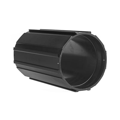
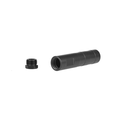
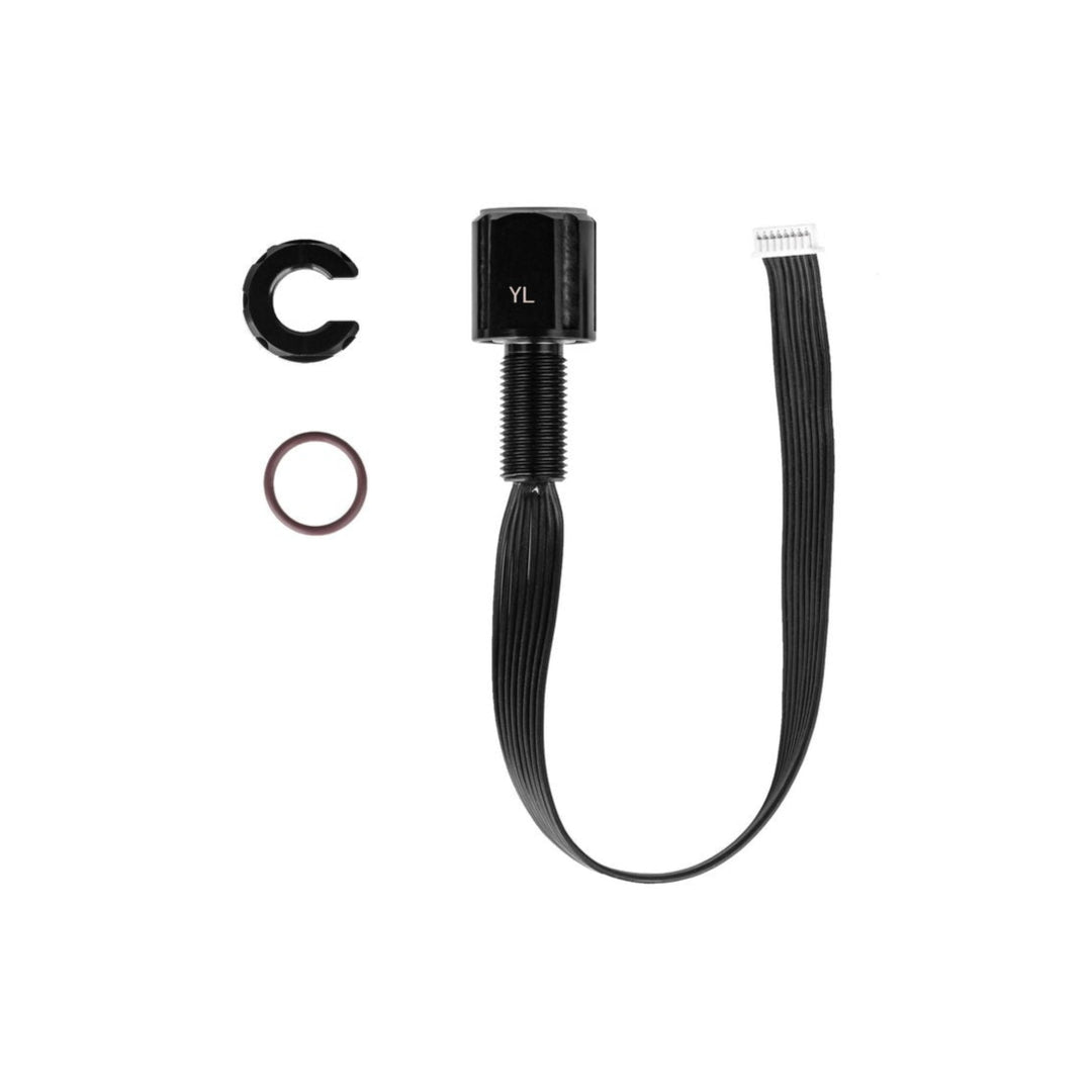
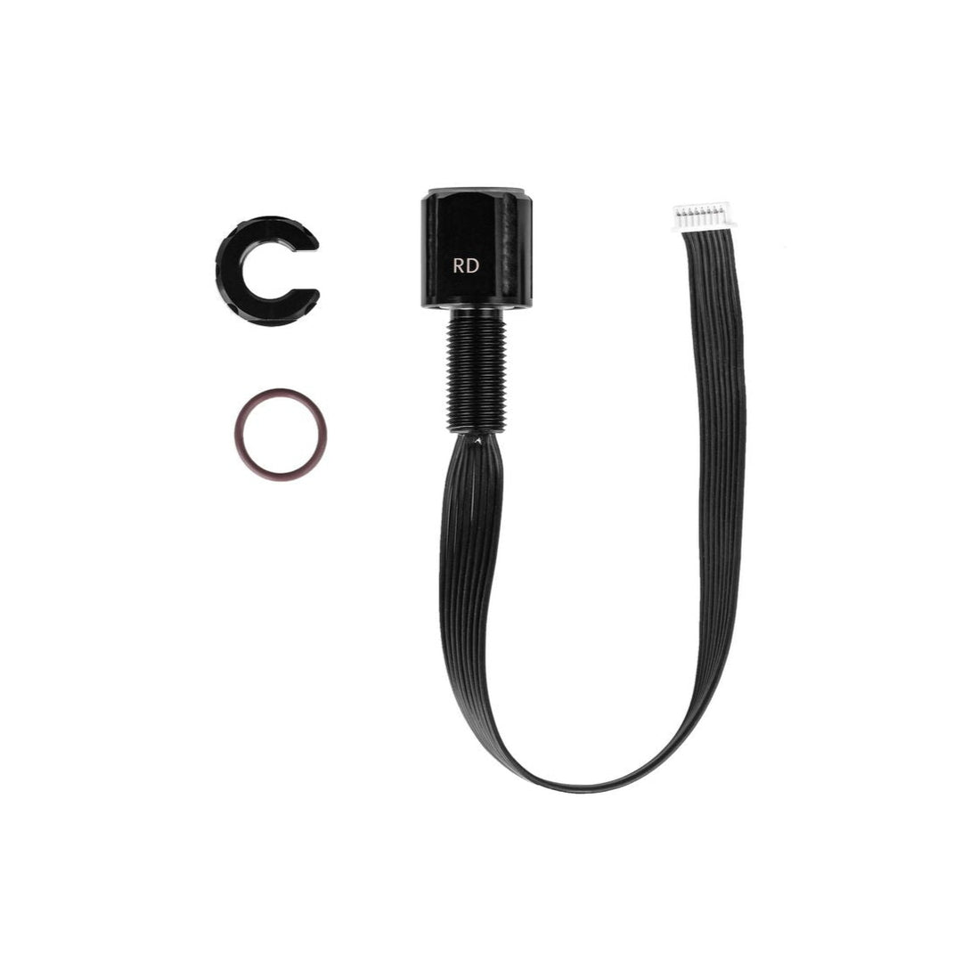
Subsea M10 Coupling Tube
Allows the 7-Segment Display to be mounted independently of a fixed enclosure, making it easy to reposition or relocate the display as needed within your subsea system. Features a single M10 threaded port and internal space for splices or strain relief.

The Subsea M10 7-Segment Display can be securely mounted into Blu-Sub enclosure systems using an Aluminum End-Cap with Aluminum Flange or a Subsea Polymer Flange & End-Cap.
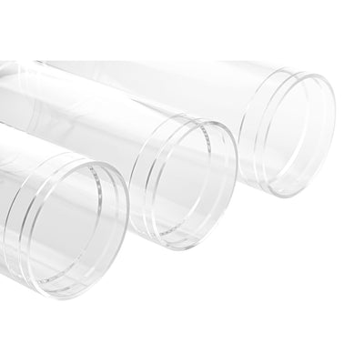
Subsea Enclosure Acrylic Tube
Constructed from cast acrylic, this transparent tube offers a durable option for visual monitoring and compact subsea assemblies. It is pressure-rated for depths between 20 m and 250 m, depending on length and size. Chamfered ends ensure a precision fit with flanges, while optional vacuum retention increases sealing strength. Ideal for shallow to mid-depth systems that benefit from internal visibility and sealed integration.
Subsea Enclosure Aluminum Tube
Made from corrosion-resistant black anodized aluminum, this rugged tube is engineered for high-pressure and long-duration underwater deployments up to 1,000 m depth. It features side locking ports for secure flange attachment in high-vibration or vertical mount scenarios. Unlike acrylic, the aluminum body is UV-stable and ideal for sunlit or surface-exposed installations, as well as deep-sea ROVs and tethered sensor systems.
This product can be installed using the Universal M8/M10 Installation Wrench, a dedicated tool designed for Blu-Sub M8 and M10 bulkhead-style components such as penetrators, switches, sensors, and connector-style hardware.
Its compact dual-end design allows installation in tight or closely spaced layouts, while cable-pass slots allow the wrench to slide over pre-attached cables, enabling installation or servicing without disconnecting wiring.


| Product | 7-Segment LED Display |
|---|---|
| Pressure-resistant Depth | 1,000 meters / 3,281 feet |
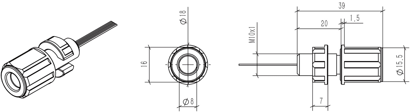
| Thread Size | M10×1 |
| Display Digits | 1 |
| Display Color | Yellow / Red |
| Display Size | 0.28 inches |
| Penetrator Material | Anodized Aluminum |
| Wire Length | ~200 mm |
| Interface Specification | 1.25 mm - 8 Pin |
| LED Voltage Range | 1.7–2.4 V |
| Forward Current | 20 mA |
| Forward Pulse Current | 60 mA |
| Backward Voltage | 5 V |
| LED Polarity | Common Anode |
| Brightness | Yellow: 105 mcd; Red: 22 mcd |
| Operating Temperature | -10 to 60 °C |
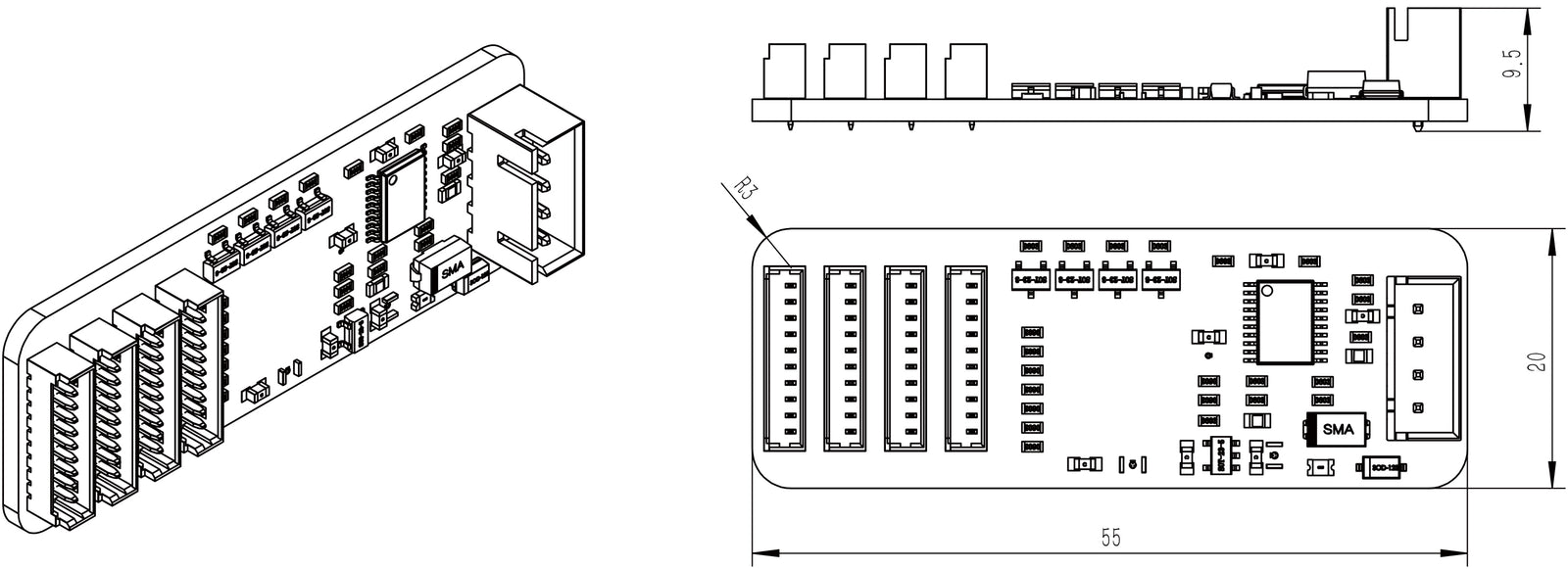
| Driver Board Size | 20 × 55 mm |
| Driver Board Voltage | 5 V |
| Driver Board Current | 0.2 A (max) |
| Driver Board Interfaces | 4 |
| Communication Method | USART (TTL) |
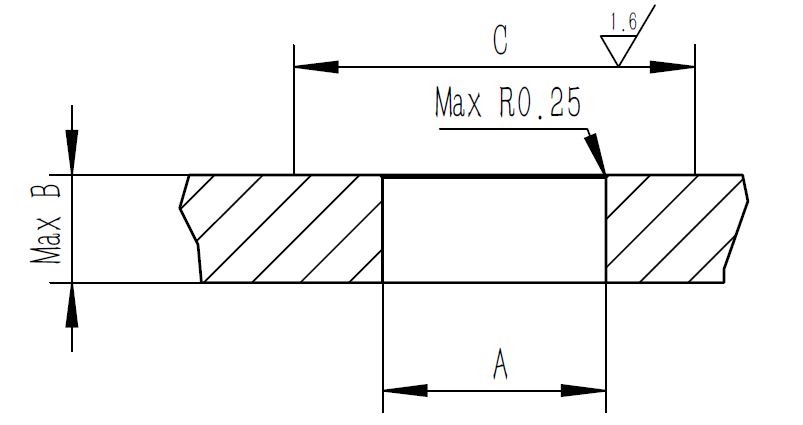
| Recommended Bulkhead Through Hole Size (A) | Ø10.1 ± 0.1 mm |
| Hatch Cover Thickness (B) | 13 mm |
| Surface Range (C) | 20 mm |
Dimension drawings for both the 7-segment LED display and driver board are provided below for reference.
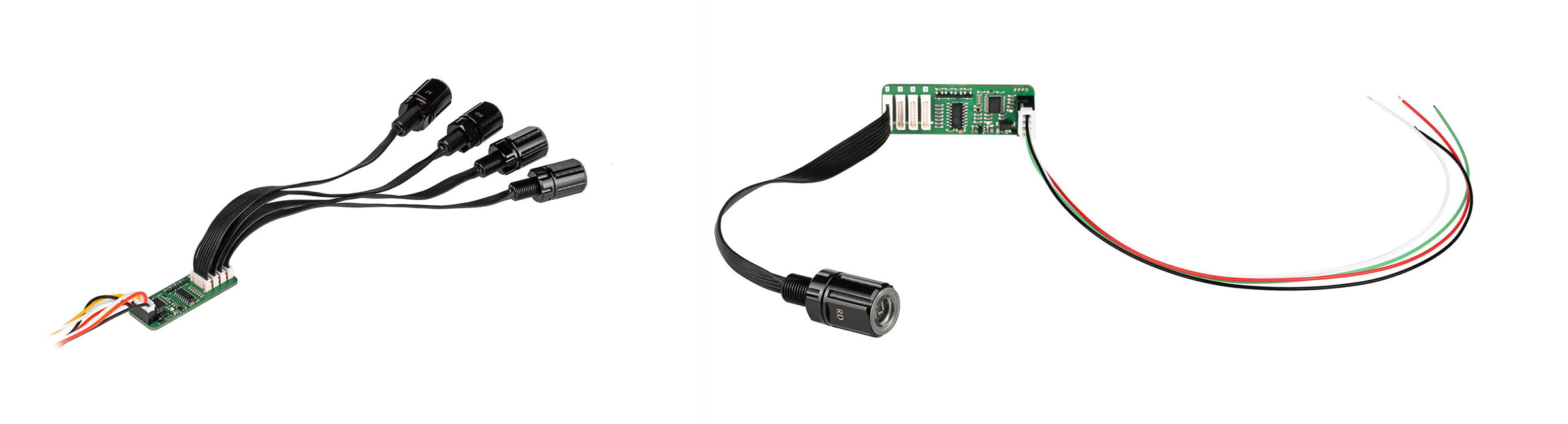
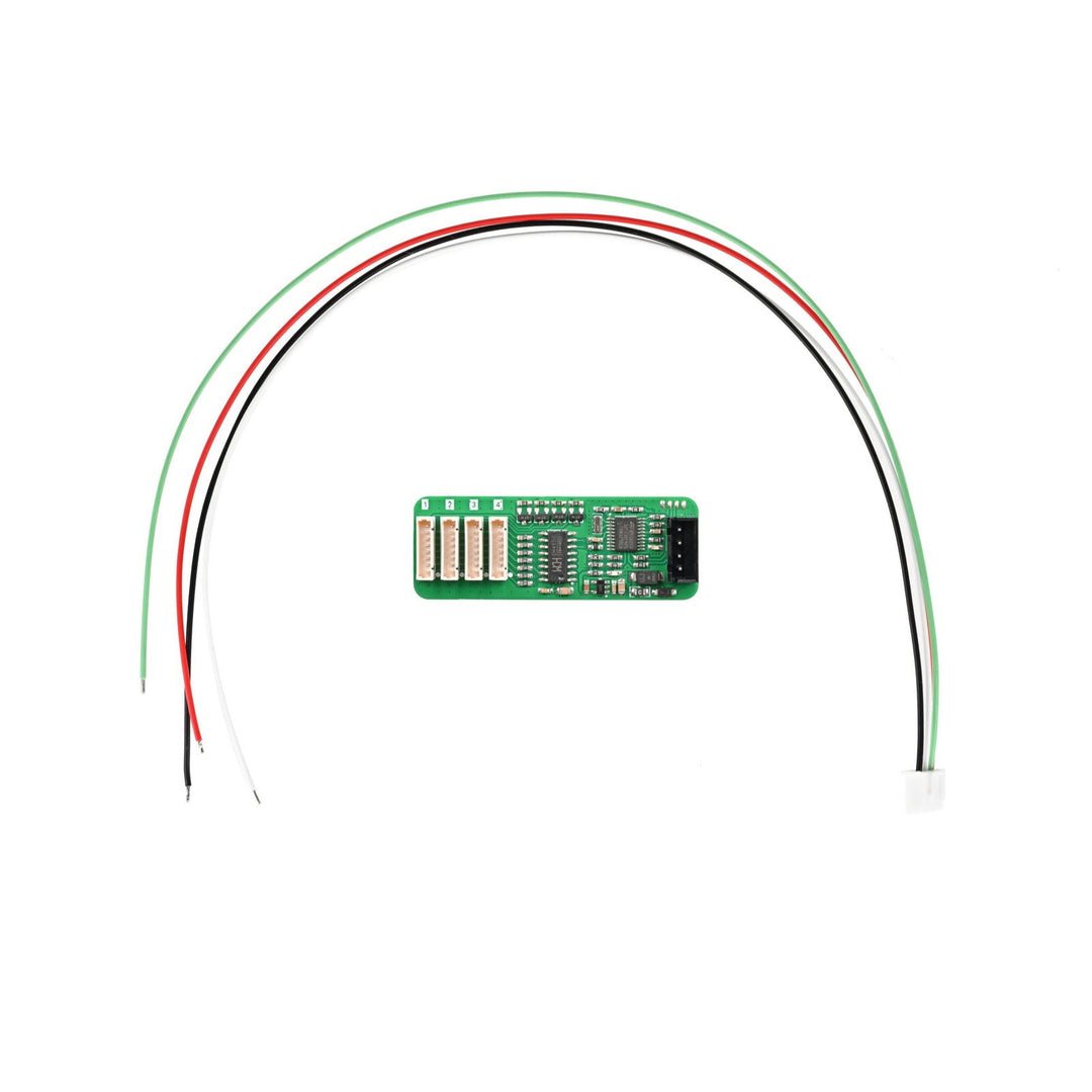
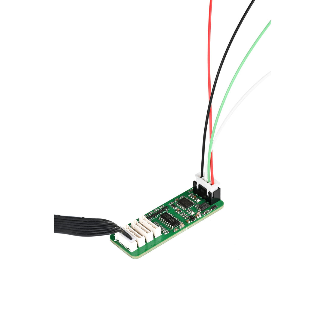
Interface Definition:
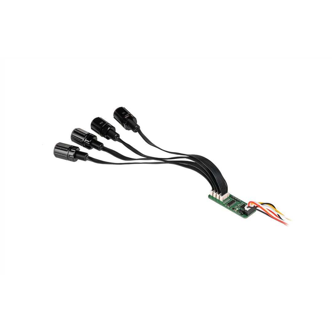
The digital tube driver board can configure parameters and control the display of 1 to 4-digit 7-segment common anode digital tubes by sending strings via a serial port. It features 8-level adjustable brightness. The display range for a single digital tube is 0–9 and A–F. Values outside this range will not be displayed.

| Label | Wire Color | Name | Function Description |
| 1 | Black | - | Power Supply Negative |
| 2 | Green | RX | Serial Port Transmit (RXD) |
| 3 | White | TX | Serial Port Receive (TXD) |
| 4 | Red | + | Power Supply Positive (5V DC) |
Connection Between Digital Tube Driver Board and External Controller:
| External Controller | Digital Tube Driver Board |
| 5V | 5V |
| RXD | TXD |
| TXD | RXD |
| GND | GND |
Serial Port Parameters:
| Communication Interface | TTL |
| Baud Rate | 115200 bps default, adjustable |
| Data Bits | 8 |
| Stop Bits | 1 |
| Parity Bit | None |
Parameter Command Configuration Table:
| Serial Command | Description | Default Value | Remarks | Corresponding Hexadecimal |
| !Bx\r\n | Configure sensor serial communication baud rate | 0x07 | x is the set baud rate value | 21 42 x 0D 0A |
| !Lx\r\n | Configure digital tube display brightness | 0x08 | x is the display brightness level | 21 4C x 0D 0A |
| !Tx\r\n | Configure onboard indicator status | 0x02 | x is the display status | 21 54 x 0D 0A |
| !Sxxxx\r\n | Configure digital tube display command | None | xxxx is the digital tube display value | 21 53 x x x x 0D 0A |
| !R\r\n | Reset digital tube driver board | None | \ | 21 52 0D 0A |
| !r\r\n | Restore all initialization settings | None | \ | 21 72 0D 0A |
Parameters configured on the digital tube driver board will be saved. The configuration data remains effective after a power cycle.
Baud Rate Table:
| Baud Rate | Value (x) |
| 2400 | 0 |
| 4800 | 1 |
| 9600 | 2 |
| 14400 | 3 |
| 19200 | 4 |
| 38400 | 5 |
| 57600 | 6 |
| 115200 | 7 |
| Other | 115200 |
Example:
Set serial port baud rate to 115200: !B7\r\n
Corresponding hexadecimal: 21 42 37 0D 0A
Display Brightness Table:
| Brightness Level | Value (x) |
| Brightness 1 | 1 |
| Brightness 2 | 2 |
| Brightness 3 | 3 |
| Brightness 4 | 4 |
| Brightness 5 | 5 |
| Brightness 6 | 6 |
| Brightness 7 | 7 |
| Brightness 8 | 8 |
| Maximum Brightness | Other |
Example:
Set brightness to level 8: !L8\r\n
Corresponding hexadecimal: 21 4C 38 0D 0A
Onboard Indicator Status Configuration Command:
!Tx\r\n
| Status | Value (x) |
| Constantly Off | 0 |
| Constantly On | 1 |
| Blinking | 2 |
Example:
Set indicator to off: !T0\r\n
Corresponding hexadecimal: 21 54 30 0D 0A
Digital Tube Display Configuration Command:
!Sxxxx\r\n
xxxx is the digital tube display content.
Example:
Display “AB12” on the digital tube: !SAB12\r\n
Corresponding hexadecimal: 21 53 41 42 31 32 0D 0A
7-Segment LED Display Pin Definition:


| Pin Number | Pin Name |
| 1 | COM |
| 2 | G |
| 3 | F |
| 4 | E |
| 5 | D |
| 6 | C |
| 7 | B |
| 8 | A |
Can it directly display the battery power? How is it used to display the battery power level?
It is not possible to display directly. The measurement voltage and 7-segment display driver board need to be added.
Can the wires be extended?
The wires should not be too long, but can be extended to about 1 m.
How many 7-segment LED displays can be connected to the driver board?
Up to 4 LED displays can be connected to the drive board.
Is the input voltage related to the brightness?
The higher the voltage the greater the brightness, but overvoltage and overcurrent will cause damage to the LED display. Use external current-limiting resistors.
Can the interface pass through the holes on the end cap?
Bend it slightly to pass through the holes of Ø10.1 ± 0.1 mm.
Is there an internal driver board?
No. The inside is only 8 direct leads for the LED display, so an external driver board is required.